Controlled NOT gate
The Controlled NOT gate (also C-NOT or CNOT) is a quantum gate that is an essential component in the construction of a quantum computer. It can be used to disentangle EPR states. Specifically, any quantum circuit can be simulated to an arbitrary degree of accuracy using a combination of CNOT gates and single qubit rotations.
Contents |
Operation
The CNOT gate flips the second qubit (the target qubit) if and only if the first qubit (the control qubit) is 1.
| Before | After | ||
|---|---|---|---|
| Control | Target | Control | Target |
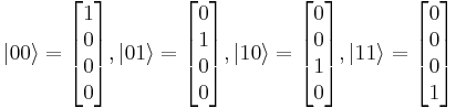
| 0 | 0 | 0 | 0 |
| 0 | 1 | 0 | 1 |
| 1 | 0 | 1 | 1 |
| 1 | 1 | 1 | 0 |
The resulting value of the second qubit corresponds to the result of a classical XOR gate.
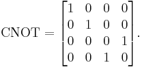
The CNOT gate can be represented by the matrix:
The first experimental realization of a CNOT gate was accomplished in 1995. Here, a single Beryllium ion in a trap was used. The two qubits were encoded into an optical state and into the vibrational state of the ion within the trap. At the time of the experiment, the reliability of the CNOT-operation was measured to be on the order of 90%.
In addition to a regular Controlled NOT gate, one could construct a Function-Controlled NOT gate, which accepts an arbitrary number n+1 of qubits as input, where n+1 is greater than or equal to 2 (a quantum register). This gate flips the last qubit of the register if and only if a built-in function, with the first n qubits as input, returns a 1. The Function-Controlled NOT gate is an essential element of the Deutsch-Jozsa algorithm. CNOT is also a kind of universal gate(in the classical sense of the word). It is easy to see that if the CONTROL is set to '1' the TARGET output is always NOT. So, a NOT GATE can be constructed using CNOT. Further, we can construct an AND GATE by using two CNOTs. Look at the table below
| Before | After | ||
|---|---|---|---|
| Control | Target | Control | Target |
| 0 | 0 | 0 | 0 |
| 0 | 1 | 0 | 1 |
| 1 | 0 | 1 | 1 |
| 1 | 1 | 1 | 0 |
| Before | After | ||
|---|---|---|---|
| Control | Target | Control | Target |
| 0 | 0 | 0 | 0 |
| 1 | 0 | 0 | 0 |
| 1 | 1 | 1 | 0 |
| 0 | 1 | 1 | 1 |
Proof of operation
Let 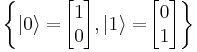 be the orthonormal basis (using Bra-ket notation).
Let 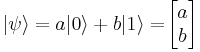 .
.
Let 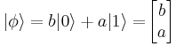 be the flip qubit of
  .
.
Recall that 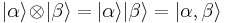 .
.
When control qubit is 0
First, we shall prove that 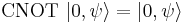 :
:
Before we compute, however, note that our specific definition of  assumes an eigenbasis of
Then, it's not difficult to verify that 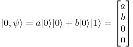
Then 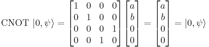 .
.
Therefore CNOT doesn't change the qubit if the first qubit is 0.
When control qubit is 1
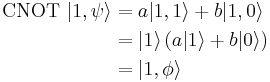
Now, we shall prove that 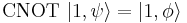 , which means that the CNOT gate flips the qubit.
Similarly to the first demonstration, we have 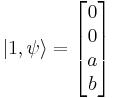 .
.
Then 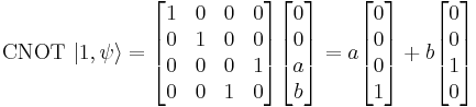
As we can see that 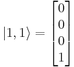 and
and 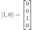 , using these on the equation above gives
Therefore the CNOT gate flips the qubit into  if the control qubit is set to 1. A simple way to observe this is to multiply the CNOT matrix by a column vector, noticing that the operation on the first bit is identity, and a NOT gate on the second bit.
References
- Nielsen, Michael A. & Chuang, Isaac L. (2000). Quantum Computation and Quantum Information. Cambridge University Press. ISBN 0-521-63235-8.
- Monroe, C. & Meekhof, D. & King, B. & Itano, W. & Wineland, D. (1995). "Demonstration of a Fundamental Quantum Logic Gate". Physical Review Letters 75 (25): 4714–4717. Bibcode 1995PhRvL..75.4714M. doi:10.1103/PhysRevLett.75.4714. PMID 10059979. [1]